by
Dave Rowe
A friction drive has several advantages over a drive that uses a worm gear for the final reduction. It has very low periodic error, in fact, so low and slow that the error is hard to measure in this mount. A friction drive combined with a well made wooden fork is extremely solid and sturdy, and can carry very large loads without flexure or vibration. Most importantly, the mount can be made at home, with a modestly equipped wood shop, a few purchased items and a bit of scavenging in the surplus shops.


This image also shows a front view of the RA drive. A stepper motor (black rectangle) drives a surplus 84:1 worm-gear reducer through a homemade coupler . A timing pulley on the output shaft of the reducer drives a timing belt that in turn drives another timing pulley. This timing belt sub-sytem has a reduction ratio of 2. The second timing pulley is coupled via a simple clutch to a 5/16" diameter friction roller. This friction drive shaft turns a large plywood/aluminum wheel, as shown in the next image. Since the wheel is 25" in diameter, the reduction ratio of the drive shaft/wheel combination is 80. Total gear reduction from the stepper to the RA axis is, then, 84 X 2 X 80 = 13,440. The stepper is used in half-step mode and has 400 half-steps per revolution. Thus, the overall reduction is 5,376,000 half-steps per rotation, or 0.24 arcseconds per half-step.
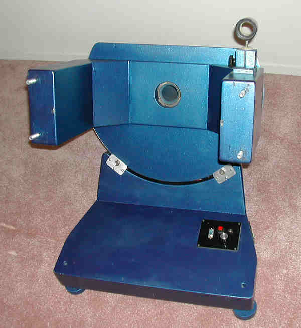
The strange little adaptor on the right fork holds a Nikon 35 mm camera lens on one side, and an ST-4 CCD auto-guider on the other side. This tiny little imaging telescope is used to perform precise polar alignment using an algorithm that I wrote in Excel. The handmade ball joint is used to roughly aim this camera at the pole.

This view also shows the aluminum flat stock that covers the outside of the plywood wheel. It is tightly stretched around the wheel then epoxied and screwed to the plywood. One of the two screws can be seen near the top of the wheel. The wheel itself was made using a router table. The wheel was routed after the aluminum-tube shaft was glued to the wheel, and before the right (north) end of the shaft was trimmed off. A 2" diameter hole in the router table, in conjunction with the shaft end, acted as the center bearing while "turning" the wheel. The wheel has less than 0.2 mm error in radius, as proved by the CCD-based polar alignment camera and numerous interesting experiments. In other words, the polar axis moves less than 2 arcminutes as the polar axis is rotated 150 degrees. This is more than good enough for very long exposure photography.
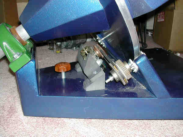
The simple friction clutch can be seen in this side view. A piece of UHMW polyethylene is sandwiched between two timing pulleys. The pulley with the timing belt is free to turn on the shaft and the other pulley is fastened to the shaft with set screws. A spring (not shown) forces the pulleys together, and causes sufficient static friction between the pulleys and the polyethylene to keep the mount in place. A few pounds of force on the forks overcomes the static friction and allows the scope to be moved to a new pointing direction. The clutch works, but it doesn't have a professional feel, and it must be kept quite tight. Suggestions for a better system are most welcome.
The brown wooden knob attaches to the threaded rod holding the rear foot, and is used for fine elevation adjustment. At this point you might be wondering how the azimuth adjustments are made. The simplest way possible -- by light taps with a soft mallet. This proves much better than having a complicated azimuth adjustment mechanism. I can quickly adjust the polar axis to within 1 or 2 arcminutes with this technique, and the mount is much stronger and lighter without the azimuth stage.

The above image shows a part of the carbon-fiber tube assembly for a large Schmidt camera. In use, a guide scope is attached to the OTA for guiding, and an ST-4 autoguider is used to make the drive corrections automatically.
The friction-drive fork mount is ideal for mounting Newtonian telescopes. I find that this mount is easier to build and stronger than a split-ring equatorial.