Making and Using a Three-ball Spherometer
by Dave Rowe
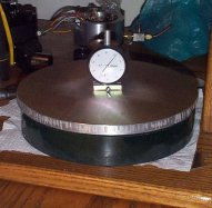 |
This image shows a 9.25" spherometer sitting on a 10" calibration flat made by the method given below. The 1/2" thick aluminum plate shown in this image was rough cut from salvaged material. On the underside of this plate are three 1/4" ball bearings on a 9.25" diameter circle. The indicator currently reads 100 microinches concave. |
Making a Spherometer Without Machine Tools
Before starting the construction of the spherometer, it is wise to first decide on the diameter of the spherometer, the required resolution and travel of the dial indicator, and to determine the required height of the balls on the spherometer so that convex surfaces of maximum sagitta can be measured without interference from the plate. In other words, think it through before starting construction. Here's the method that I employed to make several spherometers:
1) Drill a small hole in the center of a suitable plate of brass or aluminum. For a spherometer with a diameter less than 5", 0.125" thick plate is sufficient. For a spherometer up to 12" in diameter, 0.375" thick plate is more than adequate.
2) Using the small drilled centering hole and a compass, scribe two circles on the plate, one for the placement of the ball bearings and a larger circle to define where the plate will be cut. While the compass is set to the radius of the ball placement circle, scribe six marks on this circle to define the placement of the three balls. The three balls should be placed 120 degrees apart as closely as possible (but by hand is good enough).
3) Cut out the plate using a bandsaw or a hack saw.
4) Find three ball bearings (of the same size) with a diameter around 0.25" inches (smaller or larger, depending on the maximum sagitta requirements for convex and concave surfaces). Using a drill bit with about 1/2 the diameter of the balls, drill three holes at the marks.
5) From a piece of plate stock about 3/8" thick, cut out a square roughly 1" X 1". Drill a small hole (the same size as the central hole in the plate above) through this piece in its center. From the side, drill and tap a hole for a 10-24 set-screw, intersecting this centering hole. The dial indicator will be captured by the set-screw in this hole. Using a good, long cure epoxy, glue this piece to the top surface of the spherometer plate, aligning the two holes, and let the glue set. From the bottom side of the spherometer plate, using the center hole as a guide, drill out the plate and this last piece to the diameter of the dial indicator's mounting collar. (Mine has a 3/8" diameter collar.)
6) Using that good epoxy, glue the three ball bearings into the three holes made in step 4). Cleaning the items to be glued using acetone will aid in making a strong glue joint.
Determining the Spherometer's Radius
Since we have not used high-accuracy machining to place the balls, we will now have to determine the actual radius of the circle passing through the center of the balls. Using a dial caliper or other suitable measuring device with a resolution of at least 0.001", measure the ball diameter, D, and the distance between each pair of balls, A, B and C, i.e., A is the center to center distance from ball 1 to ball 2, etc. This is most easily determined by measuring the outside to outside distance between the balls and then subtracting the ball diameter. Use the following formula to determine the exact radius of the spherometer, R:

Mark the spherometer plate with the its exact radius for future reference.
Making a Calibration "Flat"
If you don't have access to a granite or optical flat, you can easily make something suitable for zeroing your spherometer by the following method:
Procure two pieces of glass larger in diameter than the spherometer, and thick enough so that they will not flex under normal usage. For spherometers up to 10" in diameter, you can use 1/2" thick plate glass cut round by your local glass supplier as long as you always use a piece of carpet underneath the glass. Other possibilities include the back sides of your mirror and tool, etc.
Grind the selected pieces together using coarser grit (I started with 220), until they are in excellent contact, flipping the pieces over after each wet. Continue to finer grits, down to about 15 microns, in this manner. Don't worry about removing the pits, just make sure that you have good contact between the pieces. This whole operation should take no more than a couple of hours if the starting pieces were roughly flat to begin with.
Now, using your newly made spherometer, measure both pieces of glass and set the dial indicator to read zero exactly between these two readings. If you have diligently flipped over the glass, the two pieces of glass should be nearly perfectly flat. When I made a 10" calibration flat in this manner, it came out with a radius of curvature of over 2 kilometers. The sagitta of each piece was about 125 microinches. Be sure to mark on the selected "flat" its exact sagitta so that later your spherometer can be re-zeroed.
Using the Spherometer
Before measuring an optical surface, be sure to zero the spherometer on the "flat", using your recorded calibration value. In the "heat of battle" I once forgot this operation and it cost me a little time to recover.
Record the measured sagitta, s, from the dial indicator, of the optic being measured. Concave surfaces will have a positive sagitta and convex surfaces will have a negative sagitta by definition. Then use the following formula to determine the radius of curvature, r, of the optic:

If the optic is concave, the radius of curvature will be positive and if convex then the radius of curvature will be negative. The above formula is exact, even for strongly curved surfaces.