 Wright Reflections
Wright Reflections
Wright ReflectionsAdditional photos of Bratislav's scope are in the Gallery.
After finally finishing my Wright camera, I thought that few people might be interested in some kind of a personal reflection on the design and execution experiences and in particular, problems encountered.
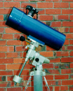
For the ones who don't know, it is a 146mm dia, 565mm f.l. (f/3.87) Wright Newtonian, intended to be primarily a photographic instrument. It has 55mm (2.14") diagonal, keeping the obstruction below 0.4. In combination with an oversized primary and ultra low focuser, it covers 35mm film with an acceptable amount of vignetting at the edges.
The Wright has several advantages over a Schmidt camera. It has flat (well, very long radius) focal plane. It is much shorter (roughly half the size of an equivalent Schmidt), and in it's Newtonian form it has an easily acessable focal plane, so it can be used with ordinary SLR cameras. Its main disadvantage is astigmatism. Ray tracing of this particular design revealed that after allowing for the vignetting, images 20mm away from axis (very corner of 35mm film) should be something like 40 by 30 microns. Inside a 25mm circle, images are as good as one can hope for (less than 20 microns). Within 10mm images are better than any CCD or film can resolve.
The primary is a rather simple story, except instead of a sphere, it's shape is oblate spheroid (the edge areas have a SHORTER radius than the center). In the original Wright design, the primary's amount of deformation is -1 (exactly the same as in an equivalent parabola, but opposite in sign, of course). The corrector is also proposed to be placed at primary mirror's focus. Such a system is aplanatic (free of spherical aberration and coma).
In this particular design I respaced the components (corrector is somewhat closer to the primary to allow easier mounting of the secondary mirror), gave the corrector little bit more power, and made a correspondingly stronger oblate. This resulted in somewhat tighter images, albeit at the price of reintroducing an insignificant amount of coma.
The corrector shape is of course "standard" Schmidt shape, approximated by:
where:
where:
I decided to tackle the problem from the other side. The commonly known (and often illustrated) Schmidt curve is but one example of the infinite number of curves that can compensate for the spherical aberration of the primary. The neutral zone can in theory be placed anywhere from 0% (dead center) to 100% (right at the edge). I looked for something with a neutral zone around 70% (quite familiar waters for an ATM). Also, I realized that this corrector is closest to a flat (it has identical height at the central and edge zone). This suited me perfectly - I could use only one tool for both sides of the corrector and grind them flat. (For the people who want to play with ray-tracing progams, the way to "shift" the neutral zone across the corrector is to scale the coefficient A. For exmaple, 1.5 times smaller "A" than calculated will get you close to the required "flat" corrector with n.z. at 70%. Good starting points for evaluation of this design are something like A = 4.574E-6 and B = -8.5827E-10).
Quick calculation showed that maximal departure from flat at the 70% zone is less than 6 microns. This seemed perfectly reachable by polishing with fast polishing pads, so I decided to polish in the correction after getting the plate reasonably flat. The small amount of curvature on the corrector doesn't matter at all - it will just attribute to minute defocusing. Anyway, armed with a precision dial indicator (Vaduz, reading down to one micron) I was ready to tackle it.
I also calculated the maximum allowable wedge on the corrector. Using Texereau's fomulae I found that this was a very loose requirement. In order to have less than a 3 micron spectra I could get away with almost 0.1mm of wedge (0.004 in). I set the limit arbitrarily to 50 microns. It it was really easy to keep it by marking the thickest side and applying the pressure there. I ended up with about 7 microns of residual wedge and about 2 microns of saggita on both sides without any dramas.
I decided to make the scope as light and rigid as possible, with particular attention to thermal stability. There is only one choice for ATM really - a composite of filler (balsawood or cardboard) and carbon fibre. That combination has a coefficient of termal expansion very nearly zero, definetely a big plus for a photographic instrument. I needed a very specific diameter, so I couldn't use a run of the mill Sonotube (or whatever).
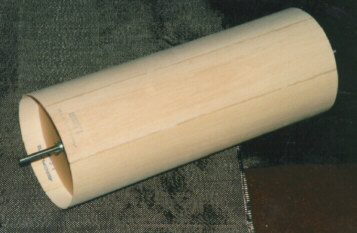
I rolled a 190mm I.D. balsa tube, 1.6mm thick (made of 100mm wide sections), and covered it with two layers of carbon on the outside and one layer inside. It turned out to be so light and strong that I decided to use this in all my future projects ! (ahem, but use Kevlar or glass fiber where thermal stability is not really an issue. They are much cheaper options with somewhat less rigidity and much more temperature dilatation). I really squeezed every millimeter out of the design by letting less than 5mm between the mirror and tube.
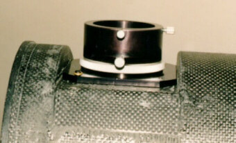
I also used a rather unortodox technique to get focal plane as low as possible by mounting the focuser below the tube's surface, taking advantage of the fact that the primary is larger than the corrector:
For the focuser base I used standard aluminum "U" channel (100mm x 25mm, 3mm thick) that I machined so it fits perfectly when placed inside the tube. Then I epoxied it using few layers of carbon to increase strength of the joint. Together with the nearby front ring that holds the corrector, it makes an extremely rigid foundation for the focuser.
The corrector holder is another composite (a loose mix of individual glass fibres cast in polyester resin). It is relatively soft and machines easy, but it is very unkind to tools!
The focuser is a low profile, non-rotating helical one, made by my friend master machinist and ATM, Stefan Buda. Believe me when I say that quite a few world class lens manufacturers would be proud if their lens focusing mechanism was as smooth and precise as this one.
The primary mirror is made from ordinary plate glass. It is 180mm dia, 15mm thick. I decided to sit it on 3 points, and it is radially fixed to prevent any movement during the exposure. Purists might cry foul at placing such a thin mirror at only 3 point support, but even visually at 140X I couldn't detect any traces of flexure. I used fast polishing pads to do the initial polishing, and a mixture of tropical pitch for figuring. Well known techniques led relatively easily to a good and smooth oblate with close to the required eccentricity. I stopped after getting an SC of -1.4 (instead of the desired -1.5) because the mirror was very smooth, and ray tracing showed almost no penalty for off-axis aberrations if the corrector was figured to match. This had an additional bonus of requiring a weaker corrector!
The corrector proved to be a tough cookie for a variety of reasons. I already had the blank of junked Chance Pilkington BSC2 glass with a nice and assuring stamp "Astronomicaly Annealed" on it. It was roughly 145mm square, 14mm thick. I sawed off the corners using one of those abrasive rods (used for cutting tiles etc.) and roughed in the circle on a rotating spindle using a grinding stone and #120 carbo.
I decided to drill the central hole (for fixing the secondary) before rough grinding. A biscuit cutter went quite fast thru the glass. I decided to drill from both sides, and leave a connecting "ring" only 2mm thick in the middle of the corrector, thus avoiding the messy procedure of gluing the central bit back in.
I used the plaster/tiles combo for grinding both sides at once. With constant interchange:
Then Mr. Murphy struck...
After another hour of polishing my heart stopped - in the middle of a stroke I felt a painfully familiar "grinding" feel. I lifted the tool in vain and saw 3 fat scratches right across the corrector face. The glass had actually chipped at the central hole, the bevel around the hole all but disappeared quite unnoticed during fine grinding. ARRGH! Back to #400. I also realized that I had to regrind the other side as well, having only one tool that had to match perfectly. Well, it wasn't that bad - I finished grinding with 5 micron aluminum oxide the same evening.
Because of work commitments I left the whole thing in the closet for more than a month. Big mistake! After some time I got back to the polishing. Looking at the progress I concluded that 2 hours polishing each side should be more than enough to clear all the pits. One thing started to bother me though. The center was polishing incredibly fast compared to the edges, no matter if tool was on top or bottom. I continued with polishing though. The weather was cloudy so I didn't have a chance to try it again as an optical window in front of my 8". A few days after (with corrector edges still a bit grayish) it cleared. Shock! Horror! I was looking at the weirdest Ronchigram I've seen in years (the "S" figure I saw once at our club's meeting still holds firmly in first place). I was really in shock. What happened? Then it dawned on me. I quickly fetched the spherometer and placed it on the corrector. 25 microns concave! The other side was even worse - 30 microns concave! I ripped the polishing pads from the tool. It was a full 50 microns convex! My notes after the fine grinding read "tool 2 microns concave". The plaster tool has changed its shape over time, and judging by the mess I ended up with, it did it most non-uniformly.
Back to grinding again. This time I left the fine grinding to be done in the morning, so I could finish polishing the same day. I also made the setup so I could try the whole camera using my 8" to provide the "starlight" (a parallel beam), and I could look at the Ronchi directly at Wright's focus, thus completely independent from freaky Melbourne weather. This time I didn't give a chance to Mr. Murphy at all. Polishing went as planned and I ended up (finally!) with a quite nice optical window.
But as we all know, optical windows just don't work that well as Wright correctors. I needed a 5 micron deep and smooth "groove" polished in at the 70% zone. I cut some petal shaped pads (with maximum area at 70%, diminishing to zero at the center and at the edge) and glued them onto the tool. Working carefully with the corrector on top I continued with figuring. The figure slowly started getting into the shape, but the edge wasn't behaving at all. It gradually but surely went down, instead of up. Something was happening there. I ripped the petals from the tool again and made a classic ring tool. Boy, do those pads cut glass! In no time I ended up with a canyon-like groove at 70% zone, very steep looking too. But the turned down edge was still persisting, if not getting worse.
I could swear that those jars with the abrasive were staring at me from the shelf...
It actually took me quite some time to really understand what was happening there - the glass that corrector was made of seems to be exceptionally thermally sensitive. It was expanding quite a lot in contact with warm hands, and because it was handled mainly by its edge, it was obviously "swelling" there. This of course had a consequence that no matter how you try it, the corrector ends up being polished much quicker at the very edge. Until the final figuring I was polishing mostly with the tool on top, having little or no contact with the corrector. Figuring stages were done exclusively with the corrector on top (because I felt a bit uneasy with those "naked" areas of plaster/tiles). Well, this was one of the ways to learn these things ...
As one can imagine, the prospects of regrinding the corrector for the fourth time (times two in reality, don't forget that there are two sides) didn't do much good for keeping the spirits high at that stage.
In despair, I decided to whack in the old 6" corrector plate from a commercial 6" SCT that a friend pulled apart. It was laying around for quite a while, but I didn't want to use it because it was made of plate glass, and, well, I don't have to tell you exactly how I feel about SCTs... just wanted to see how that one looks in the setup. I couldn't get it into Wright's corrector cell because it was larger (152mm), so I just placed it inside the Newtonian's tube, leaning it against the spider. I was quite surprised how smooth it looked; frankly I was expecting much worse. Also, the correction was very close to the one required for the Wright - the Ronchi lines diverged very gently. Dumb luck? Maybe, but I decided that this was well worth pursuing. I quickly made a small tool from a piece of wood covered with very soft pitch. After only 30 minutes of elliptical strokes around the 70-80% zone things started to look much better. Ronchi lines straightened up, and after another session I could hardly detect any line bending at all! Later, star tests showed some residual spherical aberration and a somewhat rough surface, but images were well within the required 10 microns (measured indirectly by double star observing).
Test exposures showed tight and round images. 1 minute exposure of Omega Centauri swarmed with hundreds of tiny specks, limited only by the resolution of the film. On an image of the busy Sagittarius area, stars in the corners did show some softening, as expected, but still looked quite good. Any star brighter than just above detection level would swell enough to cover up the slight elongation (slightly asymmetric images in the very corner are a combination of astigmatism, vignetting and a little residual coma). Initial tests also showed that something wasn't quite square, because some corners looked better than others (the secondary placement in a system like this is very critical). Collimation of such an instrument is not a trivial affair.
Visually, I'd call this telescope a mediocre one. It never really snaps into focus at magnifications above 80x or 100x. It shows bands on Jupiter, but little else. It splits relatively close doubles, but not very convincingly. It could also resolve Omega Centauri and 47 Tucanae into thousands of stars, but a quick glance thru a real thing (my 8" stopped down to the same aperture) simply demolishes it.
Can an instrument as complex as this really be made to the highest visual standards as well? I'd say that the answer to this is yes, but it is definitely not a trivial task. As it stands now, I certainly won't be bothered trying to improve the correction to "diffraction limited" standards. Astrophotography simply does not need any better than this, and frankly there are just too many projects in line waiting for me that I consider far more important.
And yes, that piece of Chance glass will be a telescope one day. Probably a window for a small Cassegrain or Dall-Kirkham. I just want to keep it out of sight for a while.
Bratislav Curcic
Back to Telescope Plans
Back to Home Page